Applications / Data centers · AI · HPC

Data center
liquid cooling
connections.

Hose assemblies, hoses and quick disconnects for data center infrastructure, AI servers and supercomputing systems.

From rack branches to server cooling circuits, we help turn the equipment layout, coolant and mating interfaces into a clear sourcing brief.

Inside a liquid-cooled data centerSECONDARY COOLING LOOP
Illustrative data center liquid cooling connection pathA data center secondary cooling loop from CDU and rack distribution to hose assemblies, a matched quick-disconnect pair and an AI or HPC server circuit. Equipment is shown for system context, not as a completed Dongman project.CDUSecondary loopSystem contextRack distributionSupply & return branchesSystem contextHose assemblyHose + end connection A + end connection BDONGMAN CORE PRODUCTMatched QD pairService connectionServer circuitCold-plate cooling loop
CDU secondary loopSystem context
Rack distributionSupply & return branches
Hose assemblyHose + end A + end B
Matched QD pairService connection
Server circuitCold-plate cooling loop
Illustrative data center connection path. Equipment is shown for context; our supply focus is hose assemblies, hoses and quick disconnects. The selected configuration depends on the actual system.

Application industries

Data centers. AI servers. Supercomputing.

Explore the connection requirements within these liquid cooling applications. They are illustrative scenarios for requirement discussions. Final configurations depend on the actual equipment.

01 / RACK & SECONDARY LOOPS

Data Centers

Rack supply and return branches connect liquid-cooled equipment to the secondary cooling loop. The hose assembly needs to fit the actual rack layout and mating ports.

  • Rack-to-equipment connection locations
  • Hose length, routing and service access
  • Branch flow and assembly pressure-drop allowance
Explore Connection Locations
02 / SERVER & COLD-PLATE INTERFACES

AI Servers & GPU Racks

Liquid-cooled AI servers bring CPU and GPU cold-plate circuits into compact equipment layouts. Hose routing and service interfaces need to be reviewed together.

  • Server, tray and cold-plate interface details
  • Matched plug / socket and mating arrangement
  • Coolant, seals and required compatibility evidence
Explore Connection Locations
03 / COMPUTE NODES & CLUSTERS

HPC & Supercomputing

Liquid-cooled high-performance computing (HPC) clusters and supercomputing centers have equipment-specific connection layouts. Define the connection requirements for the selected equipment.

  • Compute-node and rack routing envelope
  • Coolant, operating conditions and hose grade
  • Sample checks and identification requirements
Explore Connection Locations

Where the products fit

Three places to start the conversation.

Application examples explain connection requirements. They are illustrative scenarios, rather than completed Dongman project references.

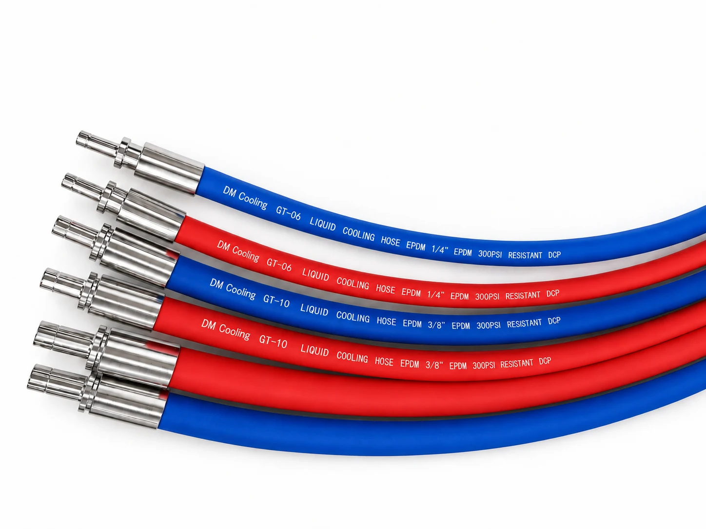
Illustrative hose assemblies for cooling connections
01 / CONNECTION LOCATION

Rack-to-equipment branches

Flexible connections between rack distribution and the equipment cooling interface.

  • Routing envelope and service access
  • Hose length, bend radius and end orientation
  • Branch flow and pressure-drop requirement
Review Hose Assemblies
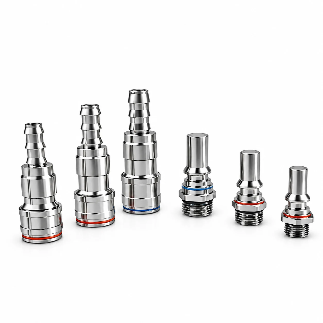
Illustrative quick-disconnect mating pairs
02 / CONNECTION LOCATION

Server & cold-plate circuits

Connections where compact geometry and serviceable mating interfaces matter.

  • Plug, socket and counterpart identification
  • Seal material and specified coolant
  • Hand-mate or blind-mate requirements
Review Quick Disconnects
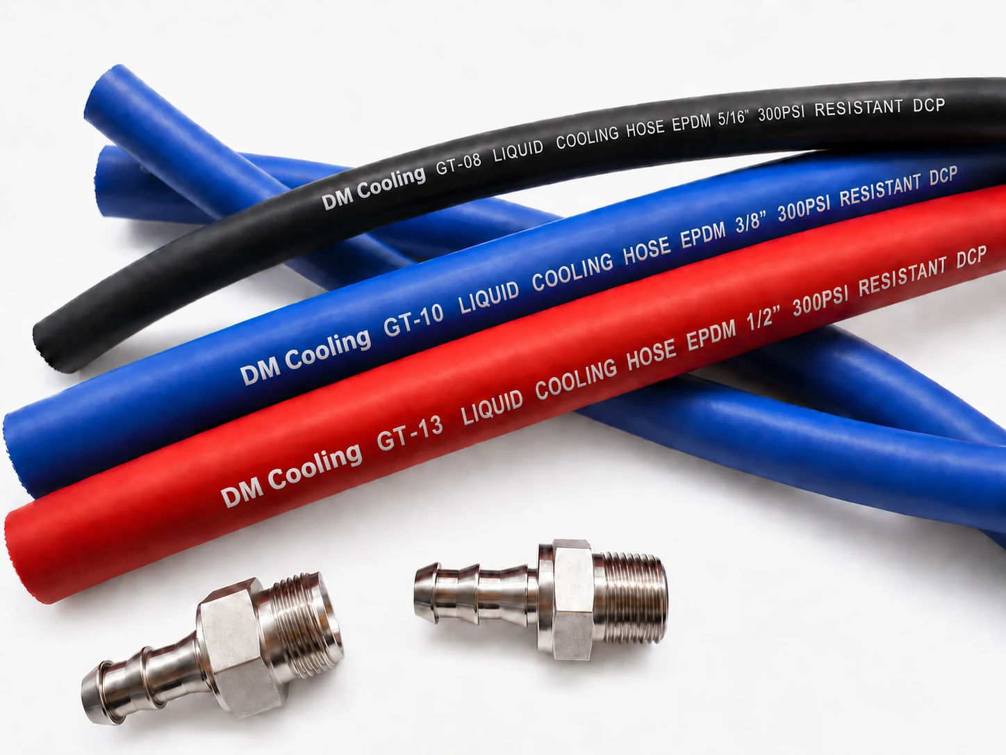
Illustrative black, blue and red cooling hoses with fittings
03 / CONNECTION LOCATION

CDU & equipment interiors

Flexible hose sections within suitable cooling equipment layouts.

  • Actual ports and available routing space
  • Hose construction and attachment method
  • Operating pressure, temperature and fluid
Review Cooling Hose

Product images illustrate possible configurations; the final hose, connectors and assembly depend on the selected specification.

Selection priorities

The location changes the questions.

A similar-looking connection can have different routing, mating and verification requirements.

Connection locationDefine firstUseful supporting information
Rack branchFlow target, hose routing, length and service spaceRack layout, mating ports and a reference assembly
Server service interfaceMating pair, connector envelope and connection methodPart numbers, dimensional drawings and interface revision
Equipment-internal loopCoolant, pressure, temperature and attachment methodPort details, hose specification and assembly drawing

Build the application brief

Show us the connection.
We can review the inputs.

A complete BOM is helpful, but a reference part, port drawing or first layout can also start the discussion.

Share a Drawing or Reference
01

Application

Where the assembly sits in the cooling loop.

02

Operating conditions

Coolant, concentration, temperature and pressure.

03

Hydraulic requirement

Target flow and the allowed assembly pressure drop.

04

Mechanical envelope

Hose length, routing space and both mating interfaces.

Supply coordination

How we take a brief forward

Review the configuration, clarify supplier information and agree the next sample or quotation step.

About Our Approach

Your enquiry

What to prepare before an RFQ

Define hose dimensions, both mating interfaces and verification requirements in your enquiry brief.

Prepare Your Enquiry

Start with your actual connection

Have a layout or a reference part?

Share the information you already have. We can identify which details are ready for sourcing and which need further confirmation.

Discuss Your Requirements